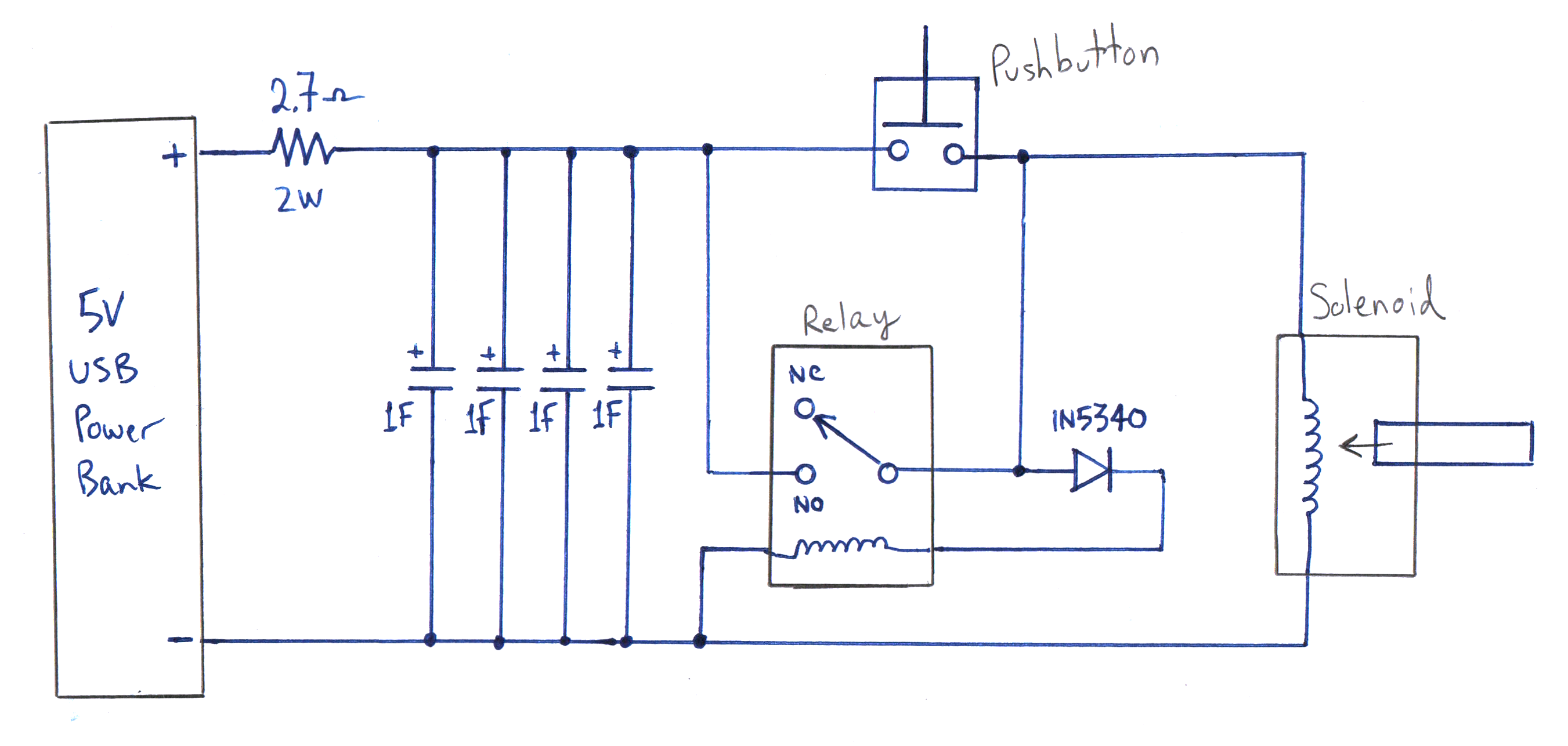
 It was then my electrical engineering brain kicked in and it occurred to me that a solenoid could
do the flush for me and it could be timed to hold down the lever for the optimal time. It didn't
take me long to come up with this circuit. There is no electrical outlet near my toilet hence the
battery powered design. I estimated that it would take a fairly high powered solenoid to pull the
lever so I chose a 44 watt solenoid from the DigiKey listings. I decided to use super-capacitors to
store the energy used to actuate the solenoid. This allows me control the duration of the flush
by changing the capacitance and also reduces the amount of current that needs to be sourced by the
voltage regulator. (The solenoid I chose draws about 8.9A when driven at 5 volts).
It was then my electrical engineering brain kicked in and it occurred to me that a solenoid could
do the flush for me and it could be timed to hold down the lever for the optimal time. It didn't
take me long to come up with this circuit. There is no electrical outlet near my toilet hence the
battery powered design. I estimated that it would take a fairly high powered solenoid to pull the
lever so I chose a 44 watt solenoid from the DigiKey listings. I decided to use super-capacitors to
store the energy used to actuate the solenoid. This allows me control the duration of the flush
by changing the capacitance and also reduces the amount of current that needs to be sourced by the
voltage regulator. (The solenoid I chose draws about 8.9A when driven at 5 volts).
 I took the plunger out of the solenoid to attach this braided wire to one end. (There is nothing holding the
plunger into the solenoid.) I also added a thin layer of felt to the pointed end. Without the felt, the solenoid
makes a sharp clacking sound as it engages. You may find the sound satisfying, although with the felt you will
barely hear the solenoid engage. As you will see in the next picture, I attached a screw to the other end of
the braided wire. Then on the other end of the screw I attached a solid copper wire which connects to the toilet
flush level. I used the screw for this purpose because it allowed me to easily adjust the tension on the wire.
I took the plunger out of the solenoid to attach this braided wire to one end. (There is nothing holding the
plunger into the solenoid.) I also added a thin layer of felt to the pointed end. Without the felt, the solenoid
makes a sharp clacking sound as it engages. You may find the sound satisfying, although with the felt you will
barely hear the solenoid engage. As you will see in the next picture, I attached a screw to the other end of
the braided wire. Then on the other end of the screw I attached a solid copper wire which connects to the toilet
flush level. I used the screw for this purpose because it allowed me to easily adjust the tension on the wire.
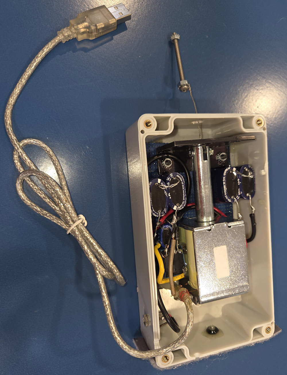
 I constructed the circuit on a small piece of vector board. This picture shows the solenoid in its fully
extended position (i.e. when there is no current in the solenoid coil). Then tension in the wire connected to
the flush lever keeps the plunger in this position (touching the plate) until the solenoid is engaged.
The black cable going to the right edge of the picture goes to a connector leading to the pushbutton and
the fat silver cable (which has a male USB connector on the end) connects to the power source.
Actually this photo doesn't show the current design (with the four 4F capacitors in series/parallel) but rather
my initial design which used four 1F capacitors in series. So the total capacitance is the same and the circuit
worked as well as my current design. The reason I abandoned that design was because I was driving the circuit
with about 5.2V but the capacitors were only rated for 5V maximum. The lifespan of a supercapacitor when it is
usually left charged to it's maximum voltage rating is already somewhat marginal and any higher than that will
shorten its lifespan even more. (I wanted a circuit that would work for several decades.) I would have replaced
the 5V capacitors with ones rated at 7 or 8 volts or more, but I didn't find any that were readily available.
Actually this photo doesn't show the current design (with the four 4F capacitors in series/parallel) but rather
my initial design which used four 1F capacitors in series. So the total capacitance is the same and the circuit
worked as well as my current design. The reason I abandoned that design was because I was driving the circuit
with about 5.2V but the capacitors were only rated for 5V maximum. The lifespan of a supercapacitor when it is
usually left charged to it's maximum voltage rating is already somewhat marginal and any higher than that will
shorten its lifespan even more. (I wanted a circuit that would work for several decades.) I would have replaced
the 5V capacitors with ones rated at 7 or 8 volts or more, but I didn't find any that were readily available.
I constructed the circuit on a small piece of vector board. This picture shows the solenoid in its fully
extended position (i.e. when there is no current in the solenoid coil). Then tension in the wire connected to
the flush lever keeps the plunger in this position (touching the plate) until the solenoid is engaged.
The black cable going to the right edge of the picture goes to a connector leading to the pushbutton and
the fat silver cable (which has a male USB connector on the end) connects to the power source.
Actually this photo doesn't show the current design (with the four 4F capacitors in series/parallel) but rather
my initial design which used four 1F capacitors in series. So the total capacitance is the same and the circuit
worked as well as my current design. The reason I abandoned that design was because I was driving the circuit
with about 5.2V but the capacitors were only rated for 5V maximum. The lifespan of a supercapacitor when it is
usually left charged to it's maximum voltage rating is already somewhat marginal and any higher than that will
shorten its lifespan even more. (I wanted a circuit that would work for several decades.) I would have replaced
the 5V capacitors with ones rated at 7 or 8 volts or more, but I didn't find any that were readily available.
Actually this photo doesn't show the current design (with the four 4F capacitors in series/parallel) but rather
my initial design which used four 1F capacitors in series. So the total capacitance is the same and the circuit
worked as well as my current design. The reason I abandoned that design was because I was driving the circuit
with about 5.2V but the capacitors were only rated for 5V maximum. The lifespan of a supercapacitor when it is
usually left charged to it's maximum voltage rating is already somewhat marginal and any higher than that will
shorten its lifespan even more. (I wanted a circuit that would work for several decades.) I would have replaced
the 5V capacitors with ones rated at 7 or 8 volts or more, but I didn't find any that were readily available.
 The previous picture (above) shows the position of the solenoid when it is not energized. The weight of the
water holds the flapper valve down which holds the solenoid in this position thru the tension in the wire
connecting the screw to the flapper valve. This picture however shows the position of the solenoid
when it is fully energized. The screw is now about 1 inch closer to the circuit board which is enough
to fully depress the flush lever. The metal plate is needed to prevent the wire tension from pulling
the plunger completely out of the solenoid. Conceivably you could use the wall of the enclosure for
this function but then you would need to be precise about where the circuit board was mounted.
The previous picture (above) shows the position of the solenoid when it is not energized. The weight of the
water holds the flapper valve down which holds the solenoid in this position thru the tension in the wire
connecting the screw to the flapper valve. This picture however shows the position of the solenoid
when it is fully energized. The screw is now about 1 inch closer to the circuit board which is enough
to fully depress the flush lever. The metal plate is needed to prevent the wire tension from pulling
the plunger completely out of the solenoid. Conceivably you could use the wall of the enclosure for
this function but then you would need to be precise about where the circuit board was mounted.
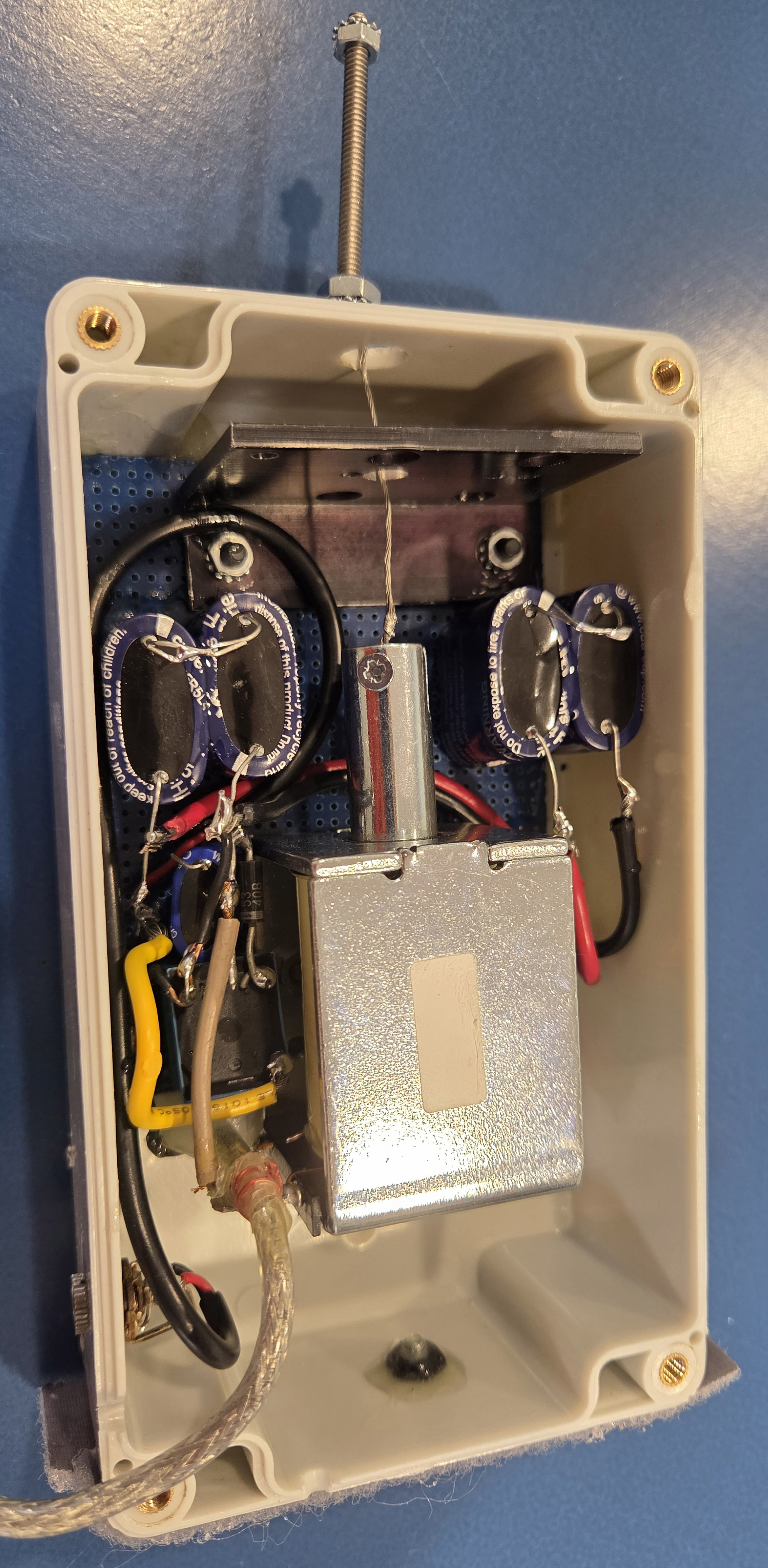 This shows the circuit board mounted inside the enclosure. (Actually I just epoxied it in.)
The connector on the side of the enclosure is for a cable going to the pushbutton. I originally put
that connector on the smaller side of the enclosure (near the right edge of this picture) but that
was when my plan was to glue the enclosure to the side of the toilet. But soon I realized that was
difficult and I decided to mount it on the floor next to the toilet. This meant I had to relocate
the connector. I plugged that hole and covered it with epoxy. I used a file to carve a small notch
in the enclosure so the silver power cable would have room to sneak thru.
This shows the circuit board mounted inside the enclosure. (Actually I just epoxied it in.)
The connector on the side of the enclosure is for a cable going to the pushbutton. I originally put
that connector on the smaller side of the enclosure (near the right edge of this picture) but that
was when my plan was to glue the enclosure to the side of the toilet. But soon I realized that was
difficult and I decided to mount it on the floor next to the toilet. This meant I had to relocate
the connector. I plugged that hole and covered it with epoxy. I used a file to carve a small notch
in the enclosure so the silver power cable would have room to sneak thru.
 After screwing the cover on, the enclosure is ready to be mounted to the floor.
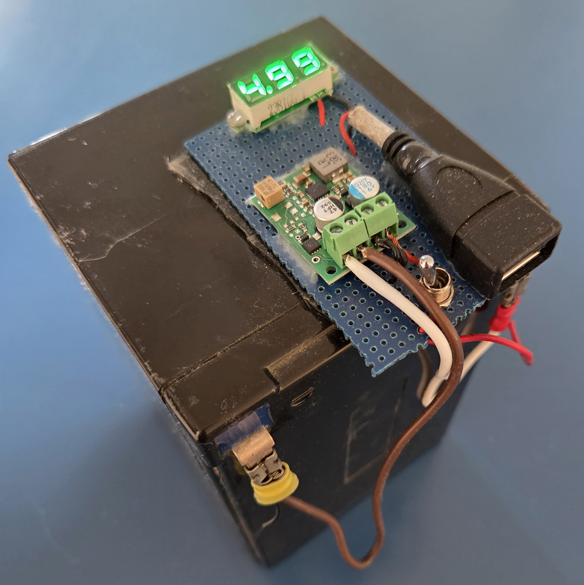
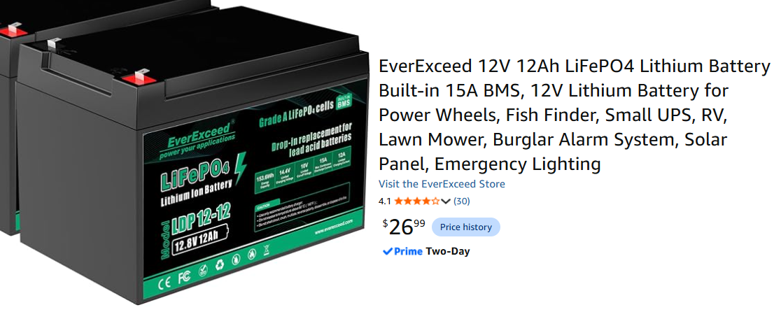
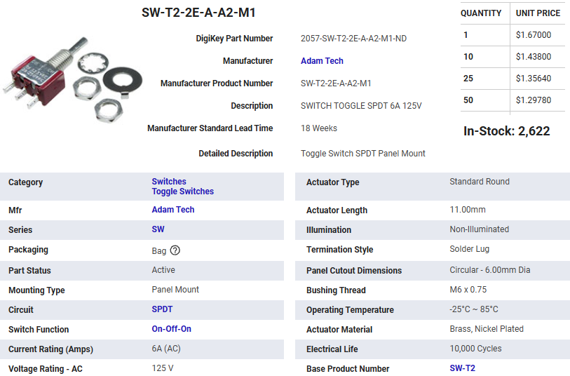
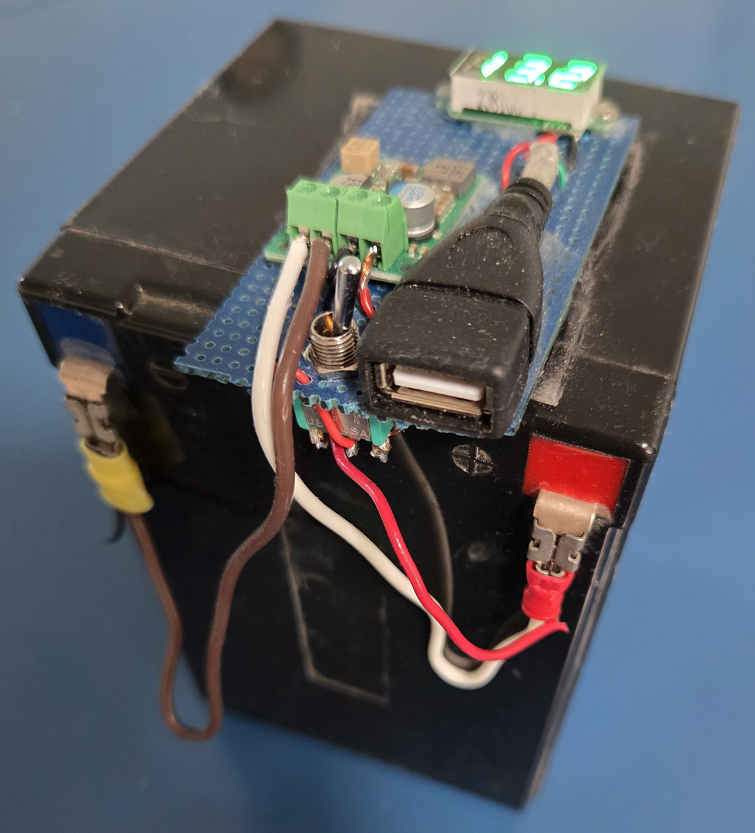 Here are two views of the battery with the voltage regulator and digital volt meter mounted
on top. When the switch is pointing away from the USB connector (as in the picture on the left)
the meter reads the voltage of the regulator output. When the switch is pointing toward the USB
connector (as in the picture on right), the volt meter displays the battery voltage. With the
switch in the middle position, the volt meter is turned off. As I mentioned before, if I were
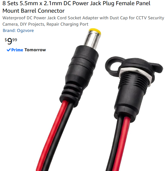
to build this again I wouldn't have a USB connector here for the power source. I would simply
connect one end of a 2-conductor cable to the circuit board and put a male barrel connector on
the other end of the cable. This would then plug into a female panel mount barrel connector
on the side of the plastic project enclosure.
Here are two views of the battery with the voltage regulator and digital volt meter mounted
on top. When the switch is pointing away from the USB connector (as in the picture on the left)
the meter reads the voltage of the regulator output. When the switch is pointing toward the USB
connector (as in the picture on right), the volt meter displays the battery voltage. With the
switch in the middle position, the volt meter is turned off. As I mentioned before, if I were
to build this again I wouldn't have a USB connector here for the power source. I would simply
connect one end of a 2-conductor cable to the circuit board and put a male barrel connector on
the other end of the cable. This would then plug into a female panel mount barrel connector
on the side of the plastic project enclosure.
 I attached the enclosure to the floor directly onto the floor so that the solenoid was aligned
under the tip of the flush lever using exterior quality Velcro rated at 15 pounds.
It's hard to see from this picture but the wire from the flush level is attached to the screw
using a crimp terminal. The tension on the wire can be adjusted by screwing the nuts towards or
away from the screw head. If you have too much tension, the flapper valve won't go down far
enough to seal the flush valve and the water will continue to run without filling the tank.
So back off the tension to allow the flush valve to close and then back off a little more allowing
a small amount of wiggle on the flush lever. The two conductor white cable is plugged into
the connector on the side of the enclosure and runs behind the toilet to the right side of the
toilet where the pushbutton is glued to the side. (See next picture). The battery with the attached
voltage regulator is not secured to the floor or the enclosure. It just sits there on the floor
making it easy to remove when it needs to be recharged. The battery I have is plenty heavy enough
that it isn't going to be wandering around, so it stays put wherever I place it. While you are
recharging the battery, you can still use the toilet by pushing on the flush lever the old fashion way.
I attached the enclosure to the floor directly onto the floor so that the solenoid was aligned
under the tip of the flush lever using exterior quality Velcro rated at 15 pounds.
It's hard to see from this picture but the wire from the flush level is attached to the screw
using a crimp terminal. The tension on the wire can be adjusted by screwing the nuts towards or
away from the screw head. If you have too much tension, the flapper valve won't go down far
enough to seal the flush valve and the water will continue to run without filling the tank.
So back off the tension to allow the flush valve to close and then back off a little more allowing
a small amount of wiggle on the flush lever. The two conductor white cable is plugged into
the connector on the side of the enclosure and runs behind the toilet to the right side of the
toilet where the pushbutton is glued to the side. (See next picture). The battery with the attached
voltage regulator is not secured to the floor or the enclosure. It just sits there on the floor
making it easy to remove when it needs to be recharged. The battery I have is plenty heavy enough
that it isn't going to be wandering around, so it stays put wherever I place it. While you are
recharging the battery, you can still use the toilet by pushing on the flush lever the old fashion way.
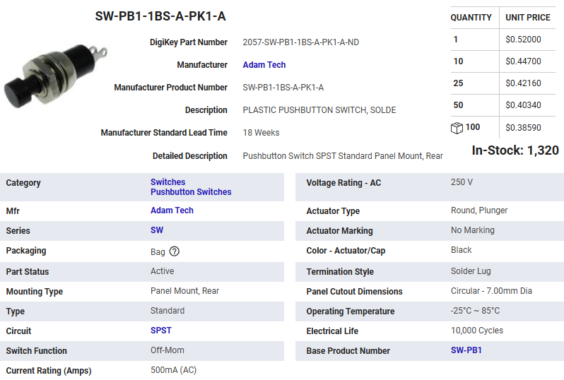
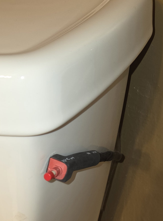 The button can be attached to the toilet in the most convenient spot for your preference. I liked
this spot on the right side just below the tank lid. I attached the button to the toilet with a
small dab of epoxy.
The button can be attached to the toilet in the most convenient spot for your preference. I liked
this spot on the right side just below the tank lid. I attached the button to the toilet with a
small dab of epoxy.
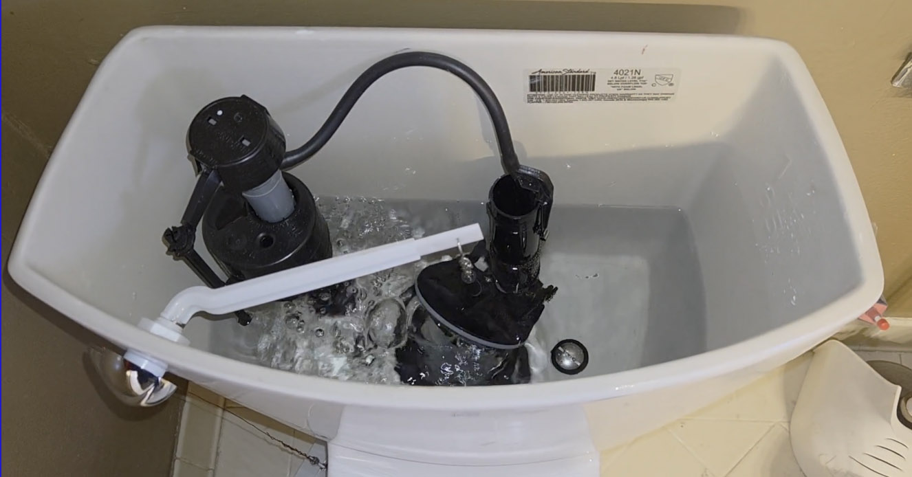
 I drilled a small hole on the underside of the flush lever and threaded the bare copper wire thru
that hole and twisted the wire to securely attach it to the lever.
I drilled a small hole on the underside of the flush lever and threaded the bare copper wire thru
that hole and twisted the wire to securely attach it to the lever.
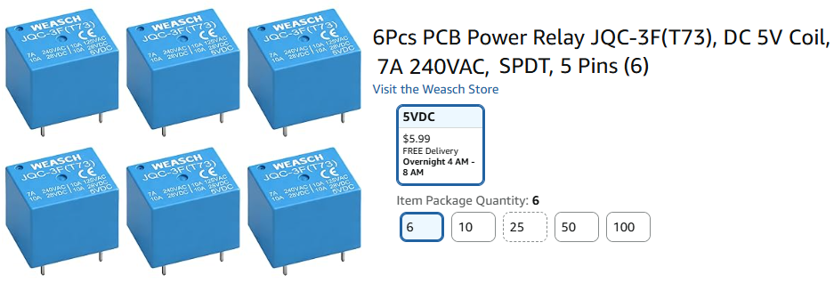
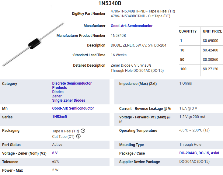
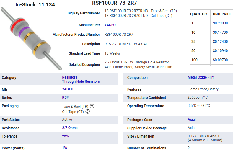
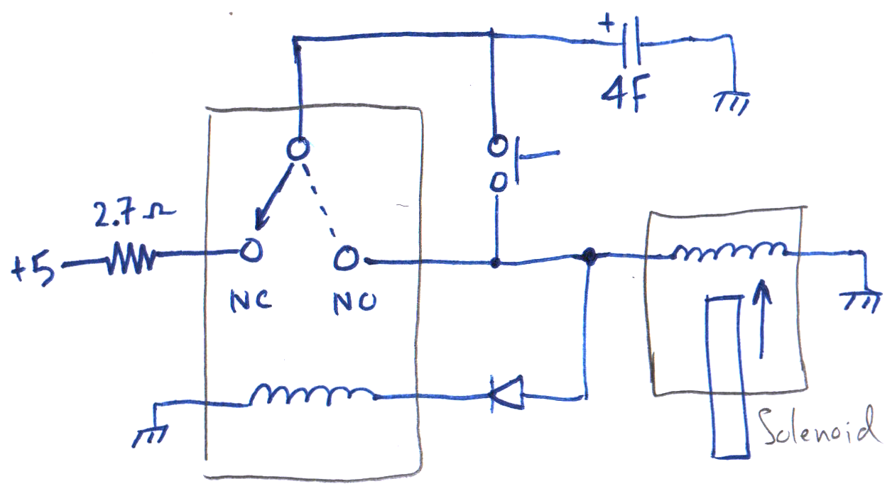 After I finished testing this design I thought of this alternative configuration for the relay,
this time using both the normally open and normally closed terminals. The advantage of this
configuration is that the power from the voltage regulator is not connected to the solenoid
while it is activated. This means you could lower the value of the resistor to allow faster
charging of the capacitors without worrying about whether the capacitors would discharge enough
for the relay to disengage. You wouldn't want to eliminate the resistor altogether since it
is still useful as a fuse to guard against the mop accidentally leaning against the pushbutton
scenario. Because the voltage regulator is no longer contributing to the energy used to keep
the solenoid engaged, the capacitor would probably have to be increased from the 4F up to
perhaps around 5F. I didn't bother testing out this circuit since my other design was working so well.
After I finished testing this design I thought of this alternative configuration for the relay,
this time using both the normally open and normally closed terminals. The advantage of this
configuration is that the power from the voltage regulator is not connected to the solenoid
while it is activated. This means you could lower the value of the resistor to allow faster
charging of the capacitors without worrying about whether the capacitors would discharge enough
for the relay to disengage. You wouldn't want to eliminate the resistor altogether since it
is still useful as a fuse to guard against the mop accidentally leaning against the pushbutton
scenario. Because the voltage regulator is no longer contributing to the energy used to keep
the solenoid engaged, the capacitor would probably have to be increased from the 4F up to
perhaps around 5F. I didn't bother testing out this circuit since my other design was working so well.
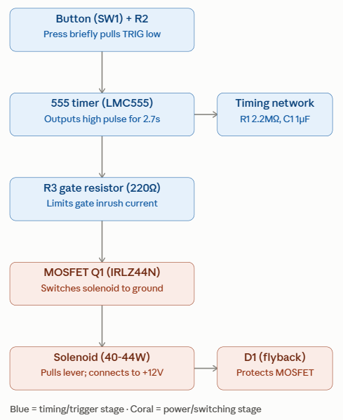
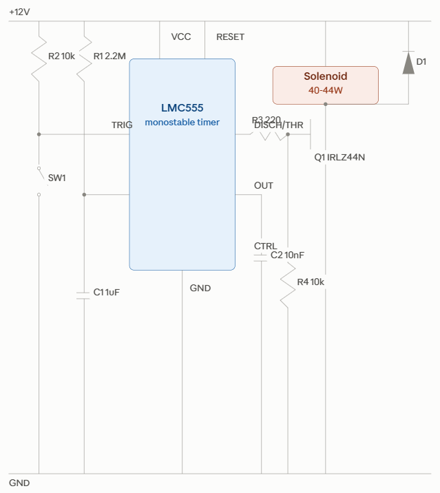
| U1 | LM555 timer | Runs fine directly off 12V |
| R1 | 2.2MΩ + 200kΩ series trim pot | trim pot lets you dial in exactly 2.7s |
| C1 | 1μF film capacitor | Timing capacitor (low-leakage/tantalum improves accuracy but isn't essential) |
| R2 | 10kΩ | Pull-up on trigger pin |
| R3 | 220Ω | Gate resistor (limits inrush into MOSFET gate) |
| R4 | 10kΩ | Gate pull-down (keeps MOSFET off at power-up before 555 settles) |
| Q1 | IRLZ44N or IRF540N (TO-220) | Logic-level N-channel MOSFET, handles the solenoid current easily |
| D1 | 1N5404 or similar (3A+) | Flyback diode — critical, across the solenoid, cathode to +12V |
| C2 | 10nF | Control voltage bypass (pin 5), standard practice |
| SW1 | Momentary N.O. pushbutton | Your trigger button |